There are quiet a few products on the market that allow us to control our bulbs and switches from our mobile phone or via a website. I wanted to see how easy it was to achieve this. After a lot of digging around and looking at options around the Arduino, I stumbled across another chip … the ESP32. It has WIFI integrated on to the board, Bluetooth support, more GPIO ports and way more goodies. There are lot of good examples available around it to on the web.
In this blog post we put together a very simple setup with the ESP32. The ESP32 will control a LED but will do so via our local network. We will look at obtain an IP on our local network and then making it a server so our Angular application can turn on and off our LED. In a future blog post we can look at converting this in a mobile app and even using AR to turn on and off the LED. Whilst we are only turning on and off an LED, in future blog post we will explore cooler extensions like motion detection sensor, camera and motors
ESP32 Setup
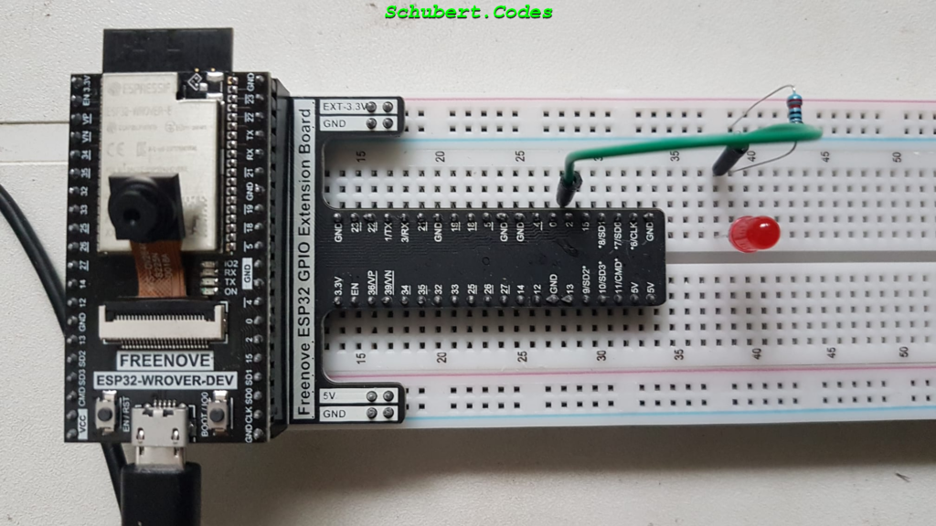
I’m using the ESP32-WROVER that I bought on Amazon. It came tightly fitted to a GPIO extension board and I didn’t want to break it prying it apart. Whilst I’m using the extension board, this is not necessary and you can get the same result using same GPIO on your ESP32. Here we have the positive of the LED connected to the output of GPIO2 and we have the negative connected to the ground via a 220 Ohm resistor

And the code to control the LED looks like this. This should make the LED switch on for 5 seconds and off for another 5 seconds and repeat this on and on
#define PIN_LED 2

void setup() {
 pinMode(PIN_LED, OUTPUT);
}

void loop() {
 digitalWrite(PIN_LED, HIGH);
 delay(5000);
 digitalWrite(PIN_LED, LOW);
 delay(5000);
}
ESP32 WIFI Code
The code to connect to your local WiFi and obtain an IP is fairly simple. We are including the WiFi library right at the start. Further down, we are calling WiFi.begin to connect to our router. If the connection is successful we should see a “Connect to IP address” message with the IP assigned to our ESP32. If you see a ‘#’ written to the COM output, it could either be the router is busy connecting or the router details are wrong. Please update your router details in the character arrays
#include <WiFi.h>

const char *routerSsid = "********"; //Enter the router name
const char *routerPassword = "********"; //Enter the router password

void setup(){
  Serial.begin(115200);
  delay(5000);

  WiFi.begin(routerSsid, routerPassword);
  Serial.println(String("Connecting to ") + routerSsid);
  while (WiFi.status() != WL_CONNECTED){
    delay(5000);
    Serial.print("#");
  }

  Serial.println("");
  Serial.println("Connected to IP address: ");
  Serial.println(WiFi.localIP());
}

void loop() {
}
ESP32 Server Code
And the final piece of the puzzle, our ESP32 needs some API endpoints that we can use to control the LED. Let create 2 endpoints, ‘/on’ and ‘/off’ and when we call ‘/on’ the LED will light up. When we call ‘/off’ the LED will switch off. And let add and endpoint ‘/status’, this can be used to get the current state of our LED. This is so we can set the initial state of our button using the current state of our LED.
Because we plan on calling this code from an Angular application, CORS enters the picture. The easiest way to get around this is to add ‘Access-Control-Allow-Origin’ and allow only certain urls. We are going to use ‘*’ here which means allow any browser to request this data. In a real world application please take the time to secure your application
#include <WiFi.h>
#include <AsyncTCP.h>
#include <ESPAsyncWebServer.h>

#define PIN_LED 2

const char *routerSsid = "********"; //Enter the router name
const char *routerPassword = "*********"; //Enter the router password

bool LedStatus = 0;

AsyncWebServer server(80);

void setup()
{
  Serial.begin(115200);
  delay(5000);

  WiFi.begin(routerSsid, routerPassword);
  Serial.println(String("Connecting to ") + routerSsid);
  while (WiFi.status() != WL_CONNECTED){
    delay(5000);
    Serial.print("#");
  }

  Serial.println("");
  Serial.println("Connected to IP address: ");
  Serial.println(WiFi.localIP());

  pinMode(PIN_LED, OUTPUT);
  LedStatus = 0;
  digitalWrite(PIN_LED, LOW);

  server.on("/on", HTTP_GET, [] (AsyncWebServerRequest *request) {
    Serial.println("switching LED on");
    LedStatus = 1;
    digitalWrite(PIN_LED, HIGH);
    AsyncWebServerResponse *response = request->beginResponse(200, "text/plain", "");
    response->addHeader("Access-Control-Allow-Origin", "*");
    request->send(response);
  });

  server.on("/off", HTTP_GET, [] (AsyncWebServerRequest *request) {
    Serial.println("switching LED off");
    LedStatus = 0;
    digitalWrite(PIN_LED, LOW);
    AsyncWebServerResponse *response = request->beginResponse(200, "text/plain", "");
    response->addHeader("Access-Control-Allow-Origin", "*");
    request->send(response);
  });

  server.on("/status", HTTP_GET, [] (AsyncWebServerRequest *request) {
    Serial.println("switching status called");
    AsyncWebServerResponse *response = request->beginResponse(200, "text/plain", LedStatus == 1 ? "ON" : "OFF");
    response->addHeader("Access-Control-Allow-Origin", "*");
    request->send(response);
  });

  server.begin();
}

void loop() {
}
Create an Angular Application
This angular application is going to be fairly simple. A component with a button. The button will show the status of the LED when it 1st loads. Clicking on the button toggles the light on and off. And this will be bases of many more complex IoT projects to come.
Create a new angular project by typing the below
ng new LedUIAppafter the node packages are download and the angular project is ready you should see something like this

Then open the project in VS code. The easy way to do this is cd into the folder and then code .
cd LedUIApp
code .
Locate app.component.html and replace its content with the below. I’m using a behavior subject to remember the LED state. Every time the status subject gets set it automatically updates the statusOpposite. Both these values are present in the component html
import { Component } from '@angular/core';
import { HttpClient } from '@angular/common/http';
import { environment } from 'src/environments/environment';
import { BehaviorSubject } from 'rxjs';

@Component({
  selector: 'app-root',
  templateUrl: './app.component.html',
  styleUrls: ['./app.component.css']
})
export class AppComponent {
  status: BehaviorSubject<string> = new BehaviorSubject('');
  statusOpposite: string | undefined;

  constructor(private httpClient: HttpClient){
    this.httpClient.get(environment.esp32LedServer + 'status', { responseType: 'text'}).subscribe(currentStatus => {
      this.status?.next(currentStatus);
    });
    this.status?.subscribe(currentStatus => {
      this.statusOpposite = currentStatus === 'OFF' ? 'ON' : 'OFF';
    });
  }

  toggleLed(){
    if(this.status?.value == "OFF"){
      this.httpClient.get(environment.esp32LedServer + 'on', { responseType: 'text'}).subscribe();
      this.status?.next('ON');
    } else {
      this.httpClient.get(environment.esp32LedServer + 'off', { responseType: 'text'}).subscribe();
      this.status?.next('OFF');
    }
  }

}
The component html should look like
<h1>Led UI App</h1>
<h2>LED is {{status.value}}</h2>
<button (click)="toggleLed()">Click here to turn LED {{statusOpposite}}</button>
I also added the ESP32 Led server as an environment variables. This can be added to your environment.ts like this
export const environment = {
  production: false,
  esp32LedServer: "http://192.168.1.251/"
};
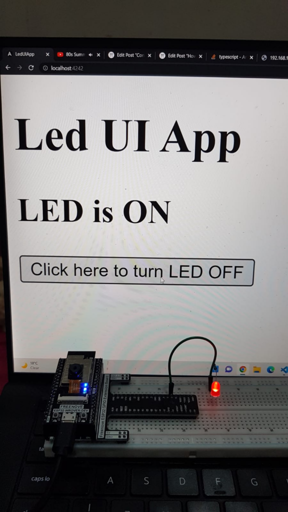
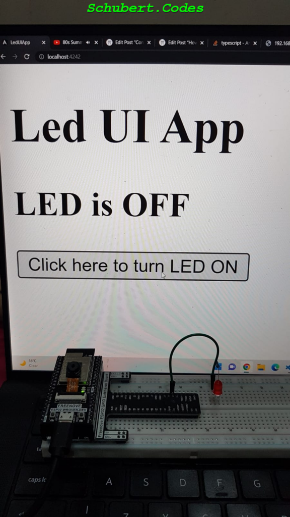
Now add the HttpClientModule to your app.modules.ts file and run your angular project using ng server. You should see something like this:

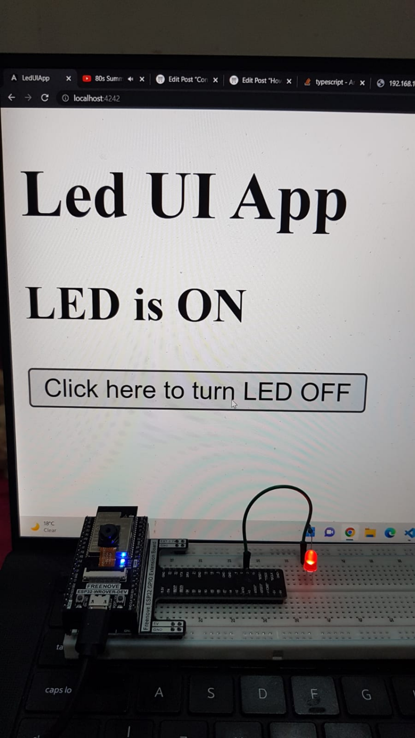
Clicking on the button should turn the LED on and off from your browser.
Final Outcome
And just like that in under an hour we are controlling an LED using an Angular Application.


Happy coding!
